rtl_fm / rx_fm: Allows you to decode and listen to FM/AM/SSB radio. rtl_sdr / rx_sdr: Allows you to record raw samples for future processing. rtl_power / rx_power: Allows you to do wideband scans over arbitrarily wide swaths of bandwidth by hopping over and recording signal power levels over multiple chunks of spectrum.
rx_tools is based on SoapySDR which is an SDR abstraction layer. If software is developed with SoapySDR, then the software can be more easily used with any SDR, assuming a Soapy plugin for that particular SDR is written. This stops the need for software to be re-written many times for different SDR’s as instead the plugin only needs to be written once.
rx_power scan with the HackRF at 5 GHz over 9 hours.
Mario Filippi, a regular contributor to our blog and to the SDR community recently wrote in with an article showing how he built an S-Band (2 – 4 GHz) antenna for use with the HackRF. Of course the antenna can be used with any other SDR that can receive in this range, or with an RTL-SDR and downconverter. We post his article below.
S -Band Antenna for use with the HackRF One Author: Mario Filippi, N2HUN
Ever since purchasing a HackRF One, which receives from 1 MHz – 6.0 GHz I’ve always wanted to explore the world above 1 Gig, specifically the 2.0 – 2.7 GHz portion of the S-band. This portion of the band is populated with satellite communications, ISM, amateur radio, and wireless networks. A good, homebrew antenna for S-band was needed, so with parts mostly from the junk box, a 2250 MHz S-band right hand circularly polarized omni-directional antenna was built. Below is a step by step tutorial on building this antenna. Plans were from UHF-Satcom’s site.
The final S-band antenna
Step 1: Take a 12” x 12” galvanized plate a mark with diagonal lines to find the center.
Mark the center of the plate
Step 2: Using a scribe, trace a 130 mm diameter circular pattern onto the plate.
Trace a 130mm circle from the center
Step 3:Cut out the circle with tin snips.
Cut our the circleThe resulting 130mm circle
Step 4: For the coil, solid copper antenna wire is used and turned around a 31 mm diameter pill bottle, resulting in a coil approximately 40 mm diameter.
Wind copper wire to create a coilThe resulting roughly shaped coil
Step 5: To space the turns 27 mm apart two heavy plastic drinking straws are marked at 27 mm intervals.
Mark two straws at 27mm intervals
Step 6:Drill holes at each 27 mm mark.
Drill holes into the 27mm marks
Step 7: Thread the coil through the two straws and allow it to sit for a few days to get into shape.
Thread the copper wire through the straws
Step 8: A 2mm thick Plexiglass™ piece was marked so each straw would be 40 mm apart, then the bottoms of each straw were set in place with gobs of hot glue. Coil turns were hot glued at straw holes.
Straws spaced 40mm and glued onto plexiglass
Step 9: Plexiglass™ piece and straws were hot glued to the 130 mm ground plane and a hole was drilled for an F connector later on. Coil was soldered at bottom to center pin of F connector.
Glue the plexiglass onto the 130mm ground plane
Step 10: Add a coat of paint to make it look a lot better! Attach the antenna to a gooseneck suction cup mount with Velcro®. Mount on an outside window, and it is now ready for action! RG/6 coax was used.
S-Band antenna paintedS-band antenna mounted
Note that the dimensions of the coil were approximate to the dimensions specified in the UHF-Satcom plans. Since this antenna was for receive only, I did not sweat the measurement details. Hot glue was used since this was a prototype to be used only on occasion and not when the weather was inclement. The omni-directional design was chosen instead of the LHCP/satellite dish combo (both plans are outlined in the UHF-Satcom site) because I wanted to receive signals from all directions. And since the HackRF One has a built-in preamplifier, an outboard in-line filter was not used.
This may not be the best or only way to construct an S-band antenna; surely other more mechanically/electronically gifted individuals will do a much better job. Initial testing shows that the little antenna, when adjusted in different directions, is picking up actual signals in this portion of the band. You can test that by looking at a signal on the waterfall, then disconnecting the antenna; if the signal remains then you may have a spurious signal from the receiver. I hope this article encourages others to look above 1 Gig mark on the spectrum. You don’t need a HackRF One necessarily as most SDR dongles cover up to at least 1.6 GHz. With a dongle you can explore other bands such as the L-band ( 1 – 2 GHz) using the right antenna and preamp; check previous articles in this website (www.rtl-sdr.com) for details. A hearty thanks to the folks at UHF-Satcom for their S-band antenna plans and information.
Over on his YouTube channel user Gareth has uploaded a video that shows a full tutorial on quickly decoding an On Off Keyed (OOK) signal with a HackRF (or RTL-SDR) and the Inspectrum software. Once decoded he then shows how to use a Yardstick One to duplicate the signal.
Inspectrum is a Linux based program that allows you to easily determine various parameters of a digital modulated signal by positioning an overlay over the waveform of a signal recorded with an SDR. Basically Gareth’s process is to first extract signal level values using Inspectrum, then secondly use a simple Python program to turn these values into binary bits, which gives him the data packet. He is then finally able to write another quick Python program to interface with the Yardstick One and retransmit the string.
The Yardstick One is a multipurpose radio (not a SDR) for transmitting modulated signals like OOK.
Earlier this week wired.com released a story indicating that researchers from the University of Birmingham have discovered two vulnerabilities that can be used to unlock almost any car. The first vulnerability concerns Volkswagen Group vehicles (VW, Audi, SEAT, Skoda) sold since 1995. Essentially their research found that the keyless entry systems of VW Group vehicles relies only on a few global master keys which they have been able to recover through reverse engineering of an undisclosed component used in a VW car. Then by sniffing the wireless key’s signal with an RF module or SDR like the RTL-SDR or HackRF they are able to recover the cryptographic algorithms used and then using the global key clone the wireless key signal, which can then be re-transmitted with a simple Arduino.
In their second research findings, the researcher’s write how they have been able to crack the Hitag2 rolling code system which is used in many vehicles such as Alfa Romeo, Chevrolet, Citroen, Dacia, Fiat, Ford, Lancia, Mitsubishi, Nissan, Opel, Peugot and Renault. Again, the hack works by sniffing a few wireless keyfob rolling code signals with an SDR or other device. Once the signals have been sniffed a simple laptop computer can reportedly break the encryption within one minute.
Here are some interesting excerpts from the conclusions of the paper:
The results of this paper show that major manufacturers have used insecure schemes over more than 20 years. Due to the widespread use of the analyzed systems, our findings have worldwide impact. Owners of affected vehicles should be aware that unlocking the doors of their car is much simpler than commonly assumed today. Both for the VW Group and the Hitag2 rolling code schemes, it is possible to clone the original remote control and gain unauthorized access to the vehicle after eavesdropping one or a few rolling codes, respectively. The necessary equipment to receive and send rolling codes, for example SDRs like the USRP or HackRF and off-the-shelf RF modules like the TI Chronos smart watch, are widely available at low cost.
A successful attack on the RKE and anti-theft system would also enable or facilitate other crimes:
– theft of the vehicle itself by circumventing the immobilizer system or by programming a new key into the car via the OBD port with a suitable tool
– compromising the board computer of a modern vehicle, which may even affect personal safety, e.g., by deactivating the brakes while switching on the wiping system in a bend
– inconspicuously placing an object or a person inside the car. The car could be locked again after the act
– on-the-road robbery, affecting the personal safety of the driver or passengers if they (incorrectly) assume that the vehicle is securely locked
Note that due to the long range of RKE systems it is technically feasible to eavesdrop the signals of all cars on a parking lot or at a car dealer by placing an eavesdropping device there overnight. Afterwards, all vulnerable cars could be opened by the adversary. Practical experiments suggest that the receiving ranges can be substantially increased: The authors of [18] report eavesdropping of a 433 MHz RFID system, with technology comparable to RKE, from up to 1 km using low-cost equipment.
The findings were presented at the Usenix Advanced Computing Systems Association conference during August 10-12, 2016 in Austin, TX. The white paper is titled “Lock It and Still Lose It—On the (In)Security of Automotive Remote Keyless Entry Systems” and can be downloaded here. Of course they did not publish the actual VW master keys in their paper and they have notified VW and NXP who make the Hitag2 chips in advance, noting that Hitag2 had actually been broken for several years prior.
Back in February we showed how Smay Kamkar was able to bypass rolling codes with his RollJam device, however the findings by these researcher’s is different in that they are actually able to generate new rolling codes, such that a simple Arduino with transmitter can act as a second wireless remote.
A $40 Arduino which can be used to record wireless rolling codes, then transmit new ones once the encryption has been broken.
Back in September the GNU Radio 2016 (GRCon16) conference was held. GRCon16 is an annual conference centered around the GNU Radio Project and community, and is one of the premier software defined radio industry events. GNU Radio is an open source digital signals processing (DSP) tool which is often used with SDR radios.
One of our favorite talks from the conference is Micheal Ossmanns talk on his idea to create a low cost $150 RX/TX radio. Micheal Ossmann is the creator of the HackRF which is a $299 USD RX/TX capable SDR. It was one of the first affordable general purpose wide frequency TX capable SDRs. Micheal also mentions his other projects including Neapolitan which will be an add on for the HackRF which will enable full-duplex communications and Marizpan which will essentially be a single board Linux SDR using the HackRF circuit.
Another is Balints talk on “Hacking the Wireless World” where he does an overview of various signals that can be received and analyzed or decoded with an SDR. Some applications he discusses include Aviation, RDS Traffic Management Channel, Radio Direction Finding, OP25, IoT, SATCOM and his work on rebooting the ISEE-3 space probe.
RTL-SDR.com reader Syed Ghazanfar Ali Shah Bukhari from the Frequency Allocation Board in Pakistan recently emailed us to let us know a trick he’s found which lets you combine the bandwidths of two HackRF software defined radios in GNU Radio. Syed’s program is based on Oliver’s flowgraph that we posted previously, which was used to combine the bandwidth of two RTL-SDR dongles.
Syed also sent us the GRC file to share which we’ve uploaded here.
He writes:
I have used grc flow graph of Oliver as mentioned in the link :- http://www.rtl-sdr.com/combining-the-bandwidth-of-two-rtl-sdr-dongles-in-gnu-radio and modified it to be used with 2 HackRF Ones. I also shifted the two bandwidths inward by 1 MHz instead of 0.2 MHz to make a smooth continuation for a 38 MHz spectrum. Unfortunately one of my HackRF Ones has its RF Amp burnt up so I adjusted its IF and BB gain to have same noise floor as that of other HackRF One. It’s really awesome. I am sending you the diagram and grc file. The attached image is showing complete GSM900 downlink spectrum (38 MHz) in my area with active 2G and 3G signals.
First generation (1G) mobile phone technology was brought out in the 80’s and was an unsecured analogue system. These days 1G technology is completely phased out in favor of digital standards like 2G (GSM), 3G and 4G LTE and so those old 1G handsets are now useless. However, at Shmoocon 2017 presenter Brandon Creighton delivered a talk where he showed how to use a TX capable SDR like a USRP or HackRF to create your own home 1G system that allows those old brick phones to be useful once again.
The actual video of the conference talk won’t be available online until about half way through the year but the blurb read:
AMPS, the first widely deployed cellular network in the US, was old enough that it had been designed by pre-breakup Bell, yet robust enough to survive for decades in service. Unlike LTE or even GSM, it was also a protocol simple enough to be described in a fairly short specification; if you wanted to you could listen to calls with a TV tuner (or modified phone).
This is a talk on the design and implementation of gr-amps, a set of GNU Radio blocks that can turn a TX-capable software-defined radio into a base station for AMPS devices–including that brick phone in your basement. No background in SDR is necessary to follow along (but it doesn’t hurt).
Expect detours into near-forgotten phreaker history: the weaknesses that enabled phone cloning, the efforts of wireless carriers and the US government to fight exploitation, and more.
The GNU Radio code to run your own AMPS (1G) system is available on GitHub. It has been tested on a USRP and HackRF.
Over on YouTube the popular Hak5 channel has uploaded a video with several SDR related topics mentioned during Shmoocon 2017 conference.
One fun event talked about in the video was the Shmoocon wireless village SDR contest by Russell Handorf which involved wireless dog shock collars. These are collars usually placed on dogs, that emit a mild electric shock when a button on a wireless remote is pressed. This can help train the dog into better behaviors. Contestants were able to first make recordings of the wireless signals made by the shock collars. Then each contestant strapped a wireless shock collar to their leg and the goal was then to reverse engineer and understand the protocol as quickly as possible, then use that knowledge and a HackRF to shock the other contestants.
Another part of the video discuss GNU Radio reverse engineering with representatives from bastille.net who are wireless IoT security researchers. The video then goes on to interview Micheal Ossmann (creator if the HackRF) who talks a bit about his work in building an infrared (IR) software defined radio. Micheal explains how infrared is essentially just radio at terrahertz frequencies and that many SDR concepts can be applied by using a photodiode sensor. He mentions that there are several IR systems used these days, such as the common remote control, toys, and high bandwidth wireless IR headphones used in car entertainment systems and conferences. The hardware Micheal has created is called “Gladiolus” and is still in development.
Recently RTL-SDR.com reader ghostop14 wrote in to us and wanted to share his GNU Radio block and tutorial that shows how to get rid of the DC spike in GNU Radio. The DC spike is the annoying spike in the middle of the spectrum that appears no matter where you tune and shows up with almost all SDRs, such as the HackRF used by ghostop14. Software programs like SDRsharp and HDSDR have algorithms in place to filter and remove the DC spike, but until now there was no block that existed for GNU Radio.
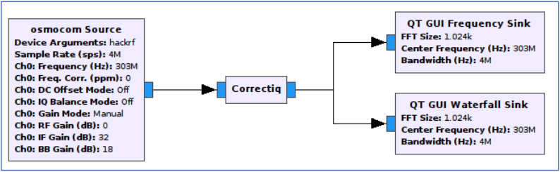
It’s your first time with gnuradio and you love your hackrf. You’ve played with receiver software like SDRSharp and audio piping to decode your favorite signal of choice, and now you’re ready to dig deeper and learn more about SDR. Everyone’s talked about gnuradio, so you install it and fire up your first flowgraph. You drop in an osmocom source block and set the device to hackrf, set your sample rate, frequency, and gain then connect it to a frequency sink and hit the button to generate your flowgraph. The ease with which you just built a receiver and the excitement about the possibilities is overwhelming… you can’t wait to hit play.
Then it happens. Right in the middle of your first flowgraph is this huge signal spike that you know is not the signal you want to receive, and as you change the frequency it follows you. What?!? So your first thought is you did something wrong. After all you’re new to gnuradio and you’re sure you’re making a newbie mistake. First you make sure there really isn’t a signal there. You go back to SDRSharp and there’s no spike. Then you swap out your hackrf for your airspy and rtl-sdr dongle, feed that into gnuradio, and there’s still no spike. What’s going on? Why is my favorite SDR that I want to use doing this? What you’ve stumbled on is an artifact of the way SDR radios do IQ sampling. Your first attempts at searching on the problem reveal that it’s called a DC spike and it’s going to appear in the raw IQ data and there’s nothing you can do to stop it. So you go back to your favorite search engine because you can’t be the first person to want to get rid of it and you find that folks say that you have 3 options: 1.) ignore it (yeah not happening. It’s huge and right in the middle of my spectrum!) 2.) Offset tune away from it on your center frequency (which means every flowgraph I make or download I’m going to have to custom change to actually get a clean center frequency signal to make them work. There has to be a better way!), or 3.) filter it out.
(cntd…)
I finally had a few hours to look into the problem further and spent the time to search and understand what was happening, and the math behind fixing it. Then researched how others were doing the same thing in their code. Turns out the solution is simple. Since the data represents an alternating RF signal, over time the signal average in a clean signal should be zero (I know I’m oversimplifying it). When there’s the IQ DC spike, that average isn’t zero. So the solution is to calculate a weighted average over ongoing samples and simply subtract it from each future sample. It doesn’t affect the overall quality of the filtered signal, but as long as the spike is on the center frequency, this approach very efficiently gets rid of it. And that was what I was hoping to accomplish.
The CorrectIQ block which gets rid of the DC spike in GNU Radio.
To upgrade to this release, you must update libhackrf and hackrf-tools on your host computer. You must also update firmware on your HackRF. It is important to update both the host code and firmware for this release to work properly. If you only update one or the other, you may experience unpredictable behavior.
Major changes in this release include:
Sweep mode: A new firmware function enables wideband spectrum monitoring by rapidly retuning the radio without requiring individual tuning requests from the host computer. The new hackrf_sweep utility demonstrates this function, allowing you to collect spectrum measurements at a sweep rate of 8 GHz per second. Thanks to Mike Walters, author of inspectrum, for getting this feature working!
Hardware synchronization: It is now possible to wire the expansion headers of two or more HackRF Ones together so that they start sampling at the same time. This is advantageous during phase coherent operation with clock synchronized HackRFs. See the -H option of hackrf_transfer. Thank you, Mike Davis!
A new utility, hackrf_debug, replaces three older debug utilities, hackrf_si5351c, hackrf_max2837, and hackrf_rffc5071.
Power consumption has been reduced by turning off some microcontroller features we weren’t using.
There have been many more enhancements and bug fixes. For a full list of changes, see the git log.
Special thanks to Dominic Spill who has taken over much of the software development effort and has helped with nearly every improvement since the previous release!
One of the most interesting updates is the upgrade to hackrf_sweep. The new firmware allows you to make huge wideband scans of the entire 0 – 6 GHz range of the HackRF in under one second (8 GHz/s). In comparison the Airspy is currently capable of scanning at about 1 GHz/s (although the Airspy author has mentioned that a sweep mode could also easily be added on the Airspy).
To update the drivers and flash the new firmware in Linux:
Flash the new firmware with hackrf_spiflash -w firmware-bin/hackrf_one_usb.bin (or the bin file for the Jawbreaker if you have that version of the HackRF)
Disconnect then reconnect the HackRF.
To install Mike Ossmanns fork of QSpectrumAnalyzer which supports the new hackrf_sweep:
To generate a wideband waterfall image sweep with hackrf_sweep and Kyle Keen’s heatmap.py software:
git clone https://github.com/keenerd/rtl-sdr-misc. Take note of heatmap.py inside rtl-sdr-misc/heatmap.
Scan from 1 MHz – 3 GHz, with a bin size of 100k, LNA gain of 32 and VGA gain of 8: ./hackrf_sweep -f1:3000 -w100000 -l32 -g8 > output_data.csv
Generate the heatmap (can take some time to complete if you have a large data file from a long scan): python heatmap.py output_data.csv heatmap_image.png
We’ve uploaded an 0-6 GHz example waterfall scan image over about 30 minutes which is available at filedropper.com/op4. The png file is 90 MB. A sample of the sweep from 400 – 600 MHz is shown below. Trunking, various telemetry and DVB-T signals are visible.
hackrf_sweep 400 – 620 MHz sample
Some GIF examples of QSpectrumAnalyzer running the new hackrf_sweep in order from 1) 0 – 6 GHz scan, 2) 0 – 3 GHz scan, 3) 0 – 1 GHz scan, 4) 500 – 640 MHz scan, 5) 2.4 GHz WiFi Band are shown below.
Thanks to Robert Terzi for the initial submission.
The Universal Radio Hacker is a software for investigating unknown wireless protocols. Features include
hardware interfaces for common Software Defined Radios
easy demodulation of signals
assigning participants to keep overview of your data
customizable decodings to crack even sophisticated
encodings like CC1101 data whitening
assign labels to reveal the logic of the protocol
fuzzing component to find security leaks
modulation support to inject the data back into the system
Inspectrum and Waveconverter are two similar programs for analyzing digital signals, however Universal Radio Hacker seems to be the most advanced.
Johannes has also uploaded four tutorial videos to YouTube which show the software in action. In the videos he uses Universal Radio Hacker to reverse engineer a wirelessly controlled power socket, and then in the last video he uses the software to transmit the reverse engineered signals via a HackRF.
After noting down the FCC ID printed on the device, they determined that the operating frequency was 315 MHz. They discovered from the documentation that each wireless DX device is encoded with a unique code that is precoded at the factory. Only remotes with the correct code programmed in can open the door.
The first attack they tried was a simple replay attack. They used a HackRF to record the signal, and then play it back again. This worked perfectly first time.
Next they decided to take this further and reverse engineer the protocol and see if a brute force attack could be applied. By doing some logic analysis on the circuit, they were able to figure out how to iterate over the entire key space. It turns out that the lock can be brute forced in at most 14.5 hours, or 7.25 hours on average.
A few weeks ago the HackRF drivers and firmware were updated and one new feature added was hackrf_sweep. This new feature allows us to scan across the spectrum at up to 8 GHz per second, which means that a full 0 – 6 GHz scan can complete in under a second.
We gave the software a test and it ran flawlessly with our HackRF. The features include:
Optimized for only one purpose – to use HackRF as a spectrum analyzer
All changes in settings restart hackrf_sweep automatically
Easy retuning
hackrf_sweep integrated as a shared library
Peak display
High resolution waterfall plot
Remember that to run the software you will need to have updated your HackRF to the latest firmware. The spectrum analyzer software is also Java based, so you’ll need to have the Java JRE for Windows x64 installed.
Over on YouTube a video titled “Hunting Rogue WiFi Devices using the HackRF SDR” has been uploaded. The talk is given by Mike Davis at the OWASP (Open Web Application Security Project) Cape Town. The talk’s abstract reads:
Rogue WiFi Access Points are a serious security risk for today’s connected society. Devices such as the Hak5 Pineapple, ESP8266-based ‘throwies’, or someone with the right WiFi card and software can be used to intercept users’ traffic and grab all of their credentials. Finding these rogue devices is a very difficult thing to achieve without specialised equipment. In this talk Mike will discuss the work he has been doing over the past year, to use the HackRF SDR as a RF Direction-finding device, with the goal of hunting down various malicious RF devices, including car remote jammers.
The talk starts off with the basics, explaining what the problems with WiFi devices are, what the HackRF and SDR is, and then goes on to explain some direction finding methods that Mike has been using.
The PortaPack is an addon created by Jared Boone for the HackRF software defined radio. It costs $200 USD at the sharebrained store and together with a USB battery pack it allows you to go completely portable with your HackRF. The HackRF is a multi-purpose SDR which can both receive and transmit anything (as long as you program it in) from 1 MHz to 6 GHz.
Since we last posted about the PortaPack many new features have been added, and the firmware has matured significantly. Now the official PortaPack firmware allows you to receive and demodulate SSB, AM, NFM, WFM and display up to an 18 MHz wide waterfall. You can also decode marine AIS, the automobile tyre pressure monitoring system (TPMS) and utility ITRON ERT meters.
There is also a popular fork of the official PortaPack firmware called portapack-havoc, which is created by a dev who goes by the handle ‘furrtek’. This firmware is a bit more risky in terms of the trouble it can get you into as it enables several new features including:
Close call – See if anyone is transmitting near to you
A CW generator
a GPS and various other jammers
an LCR transmitter – the wireless protocol used in France for programming traffic related signage
a microphone transmitter
a pocsag receiver and transmitter – receive and send to pagers
a PWM RSSI output – useful for crude automatic direction finding
an RDS transmitter – transmit radio station text data to compatible broadcast FM radios
a soundboard – play a stored bank of wav sounds on a frequency
an SSTV tranmitter – transmit slow scan TV signals
an OOK transmitter – control on-off-keying devices such as doorbells.
Below we’ve created a YouTube playlist showing several videos that show the portapack in action.
And below we show a tweet from @furrtek showing off the recently added SSTV transmit feature, and a tweet from @giorgiofox showing off the microphone transmit feature.
Last week we made a post about the HackRF Portapack, and gave some examples of it in action. Recently the furtek Havoc firmware for the portapack was updated, and it now supports SSTV transmission. Over on Twitter, Giorgio Campiotti @giorgiofox has uploaded a video showing an example transmission in action.
In the video the HackRF with Portapack transmits a test SSTV image to an Elecraft K3 ham radio, which is linked to a PC. SSTV decoding software on the PC turns the data back into an image.
SSTV stands for ‘Slow Scan TV’, and is a method used by hams to send images over radio. Typically this activity occurs on HF frequencies. Sometimes the ISS transmits SSTV images down to earth as well to commemorate special events.
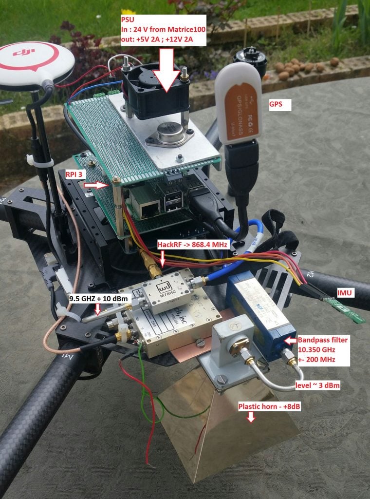
The idea is to use the drone as a remote beacon which can move all around the antenna. As the drone flies around, the HackRF on the drone emits a data chirp containing GPS telemetry of the drones position. The receiver on the ground decodes this data and also determines the SNR of the received signal. By plotting the received SNR together with the drones GPS position, the radiation pattern of the antenna under test could be determined.
The software is called “RadiantBee” and is developed by both F4GKR and F5OEO. It is available over on GitHub. The flying hardware consists of a quadcopter, GPS, Raspberry Pi 3, HackRF, 10 GHz upconverter, band pass filter and horn antenna. The base station consists of an RTL-SDR dongle, 10 GHz downconverter, GPS and the antenna under test.
Last year during a Russian wireless ‘capture the flag’ (CTF) competition one of the goals was to reverse engineer a remote controlled toy tank, and then to control it with a HackRF. One of the Russian CTF teams has posted a thorough write up on the reverse engineering process that was used on the toy tank (the link is in Russian, but Google Translate works okay).
The write up first shows the reception of the signal from the wireless controller, and then moves on to show how to receive it in GNU Radio and obtain a time domain graph of the digital signal. From the pulses it is simple to visually work out the binary string. Next an instruction decoder is created in GNU Radio which automatically obtains the binary string from the signal directly. Then once the codes for back, forward, left and right were obtained it was possible to write another GNU Radio program to transmit these codes to the RC toy tank from the HackRF.
In his submission he shares a tutorial that explains the theory behind the PAL analog video standard. He explains the different components of the PAL signal, including the luma (black and white part), frame rates, and modulation. He then goes on to explain how color is encoded onto the PAL by using Quadrature Amplitude Modulation (QAM).
Finally in the files section marble also supplies us with the GNU Radio flowgraph which can be used to transmit PAL video with a HackRF.
The HackRF is a $300 USD RX/TX capable software defined radio which has a wide tuning range from almost DC – 6 GHz, and wide bandwidths of up to 20 MHz. It uses an 8-bit ADC so reception quality is not great, but most people buy it for its TX and wide frequency/bandwidth capabilities.
Recently the HackRF received some negative press in the ‘DailMail’, a British tabloid newspaper famous for sensationalist articles. In the article the DailyMail show that the HackRF can be used to break into £100,000 Range Rover car in less than two minutes. The exact method of attack isn’t revealed, but we assume they did some sort of simple replay attack. What they probably did is take the car key far away out of reception range from the car, record a key press using the HackRF, and then replay that key press close to the car with the HackRF’s TX function. Taking the key out of reception range of the car prevents the car from invalidating the rolling code when the key is pressed.
Of course in real life an attacker would need to be more sophisticated as they most likely wouldn’t have access to the keyfob, and in that case they would most likely perform a jam-record-replay attack as we’ve seen with cheap homemade devices like RollJam. The HackRF cannot do this by itself because it is only half-duplex and so cannot TX and RX at the same time.
We should also mention that the HackRF is not the only device that can be used for replay attacks – potentially any radio that can transmit at the keyfob frequency could be used. Even a very cheap Arduino with ISM band RF module can be used for the same purpose.


 this piece on the hackRF is alongside the NHS attack in dailymail.